Fixing missing mesh faces in Unreal Engine
For the multidimensional game I’m creating, there are a couple of concepts that I need to understand, in order to efficiently develop the game. Some time ago I finished a multidimensional cube rendering using Python. It was a simple POC just to make sure I get the concept.
~Two weeks ago I decided it’s about time to try to implement the cube in the environment which is gonna be used for the game - Unreal Engine (UE). It was a journey, I must admit.
Mesh from C++
It was meant to be a simple POC, so I didn’t want to go down the rabbit hole of GPU optimizations (which I plan for the final game). I just want to be able to build a 3D mesh out of a multidimensional cube and present it in Unreal. Simple enough.
Found this great tutorial of exactly what I needed - manipulating meshes at runtime from the C++ level: https://www.gradientspace.com/tutorials/2020/10/23/runtime-mesh-generation-in-ue426
There was a minor problem that the tutorial talks about UE 4.26 and I’m using 5.2 as of now. After an evening of getting familiar and simple fixes I ported it to UE 5.2. For anyone in need, here’s a PR with the port: https://github.com/gradientspace/UnrealMeshProcessingTools/pull/9
So, far so good. I ported the code of the multidimensional cube from Python to C++, created a new Actor and placed in the world of UE. And here’s where the struggle begins.
Magic faces
When you first spawn a 4D cube there are no rotations or position change applied. It’s just a cube with edges parallel to X, Y, Z and W axes. Meaning, when we present it in the 3D world, we should expect something that looks like a regular 3D cube.
But, instead of a cool cube, UE presented me kinda cube, with half of the faces missing.
Double checked the 4D code and math and didn’t spot any bugs. After a while I realized that the faces aren’t missing. They are just invisible. They become visible once you move the camera to look from a specific angle. You can spot that in the gif. When camera orbits around, you can see that one triangle of a given cube side becomes visible, and the one that was visible a second ago goes missing.
Googled a bit and got a hint - UE won’t render a face if the normal of the face isn’t facing the camera. That makes perfect sense. But, why are my normals messed up?
Triple checked the 4D code and math. Again, spotted no bugs. All the faces and normals looked good. I had to approach this differently.
Pen and paper
So, the natural move here was to have a MCVE - minimal, complete and verifiable example. Sat down with a piece of paper, drew a 3D cube, specified an array of verticies and an array of triangles composed of the indicies of the verticies. Plus, of course, normals. Basically something like this:
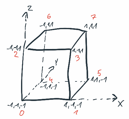
With triangles and normals:
Front side:
  tri 0: [0, 2, 3]
  tri 1: [0, 3, 1]
  normal: [0, -1, 0]

Back side:
  tri 2: [4, 6, 7]
  tri 3: [4, 7, 5]
  normal: [0, 1, 0]

Left side:
  tri 4: [0, 2, 6]
  tri 5: [0, 6, 4]
  normal: [-1, 0, 0]

Right side:
  tri 6: [1, 3, 7]
  tri 7: [1, 7, 5]
  normal: [1, 0, 0]

Bottom side:
  tri 8: [0, 4, 5]
  tri 9: [0, 5, 1]
  normal: [0, 0, -1]

Top side:
  tri 10: [2, 6, 7]
  tri 11: [2, 7, 3]
  normal: [0, 0, 1]
The mesh generation method looks like this:
UE::Geometry::FDynamicMesh3 AMyActor::RegenerateMeshByHand2() {

  UE::Geometry::FDynamicMesh3 mesh;
  mesh.EnableAttributes();

  UE::Geometry::FDynamicMeshNormalOverlay *normalsOverlay =
      mesh.Attributes()->PrimaryNormals();

  const std::array vertices{FVector3d(-1, -1, -1), FVector3d(1, -1, -1),
                            FVector3d(-1, -1, 1),  FVector3d(1, -1, 1),
                            FVector3d(-1, 1, -1),  FVector3d(1, 1, -1),
                            FVector3d(-1, 1, 1),   FVector3d(1, 1, 1)};

  const std::array normals{FVector3f(0, -1, 0), FVector3f(0, 1, 0),
                           FVector3f(-1, 0, 0), FVector3f(1, 0, 0),
                           FVector3f(0, 0, -1), FVector3f(0, 0, 1)};

  [[maybe_unused]] int32 id;
  [[maybe_unused]] UE::Geometry::EMeshResult result;

  for (auto vertex : vertices) {
    mesh.AppendVertex(vertex * 100);
  }

  for (auto normal : normals) {
    normalsOverlay->AppendElement(normal);
    normalsOverlay->AppendElement(normal);
    normalsOverlay->AppendElement(normal);
  }

  // Face 0, 1. Normal 0
  id = mesh.AppendTriangle(0, 2, 3);
  result = normalsOverlay->SetTriangle(id, {0, 1, 2});

  id = mesh.AppendTriangle(0, 3, 1);
  result = normalsOverlay->SetTriangle(id, {3, 4, 5});

  // Face 2, 3. Normal 1
  id = mesh.AppendTriangle(4, 6, 7);
  result = normalsOverlay->SetTriangle(id, {1 * 3, 1 * 3 + 1, 1 * 3 + 2});

  id = mesh.AppendTriangle(4, 7, 5);
  result = normalsOverlay->SetTriangle(id, {1 * 3, 1 * 3 + 1, 1 * 3 + 2});

  // Face 4, 5. Normal 2
  id = mesh.AppendTriangle(0, 2, 6);
  result = normalsOverlay->SetTriangle(id, {2 * 3, 2 * 3 + 1, 2 * 3 + 2});

  id = mesh.AppendTriangle(0, 6, 4);
  result = normalsOverlay->SetTriangle(id, {2 * 3, 2 * 3 + 1, 2 * 3 + 2});

  // Face 6, 7. Normal 3
  id = mesh.AppendTriangle(1, 3, 7);
  result = normalsOverlay->SetTriangle(id, {3 * 3, 3 * 3 + 1, 3 * 3 + 2});

  id = mesh.AppendTriangle(1, 7, 5);
  result = normalsOverlay->SetTriangle(id, {3 * 3, 3 * 3 + 1, 3 * 3 + 2});

  // Face 8, 9. Normal 4
  id = mesh.AppendTriangle(0, 4, 5);
  result = normalsOverlay->SetTriangle(id, {4 * 3, 4 * 3 + 1, 4 * 3 + 2});

  id = mesh.AppendTriangle(0, 5, 1);
  result = normalsOverlay->SetTriangle(id, {4 * 3, 4 * 3 + 1, 4 * 3 + 2});

  // Face 10, 11. Normal 5
  id = mesh.AppendTriangle(2, 6, 7);
  result = normalsOverlay->SetTriangle(id, {5 * 3, 5 * 3 + 1, 5 * 3 + 2});

  id = mesh.AppendTriangle(2, 7, 3);
  result = normalsOverlay->SetTriangle(id, {5 * 3, 5 * 3 + 1, 5 * 3 + 2});

  return mesh;
}
(Pssst, UE::Geometry::FDynamicMeshNormalOverlay::SetTriangle() fails if you pass there the same normal three times. That’s why I had to append the very same normal three times and assign same normals with different indices to the vertices of the triangle)
But again, got very similar result - half of the faces are invisible.
That’s weird. Good that I’m able to easily reproduce, but weird. Tried playing with normals, specifying faces in a different order and lots of other and tons of other things. Still same. At this point, I had no idea.
Pen and paper with Blender
The other day, during a cold shower (there was a heat wave over Poland, 34℃), was struck with an idea: How about I go to a 3D tool, create the simplest cube possible there, export and take a look what’s inside the exported model?
Cool. Downloaded Blender, opened it and.. Ha! The default project comes with a cube spawned. That’s convenient! Exported it to OBJ and opened in VS Code. The whole OBJ looks like this:
# Blender 3.6.1
# www.blender.org
mtllib untitled.mtl
o Cube
v 1.000000 1.000000 -1.000000
v 1.000000 -1.000000 -1.000000
v 1.000000 1.000000 1.000000
v 1.000000 -1.000000 1.000000
v -1.000000 1.000000 -1.000000
v -1.000000 -1.000000 -1.000000
v -1.000000 1.000000 1.000000
v -1.000000 -1.000000 1.000000
vn -0.0000 1.0000 -0.0000
vn -0.0000 -0.0000 1.0000
vn -1.0000 -0.0000 -0.0000
vn -0.0000 -1.0000 -0.0000
vn 1.0000 -0.0000 -0.0000
vn -0.0000 -0.0000 -1.0000
vt 0.625000 0.500000
vt 0.875000 0.500000
vt 0.875000 0.750000
vt 0.625000 0.750000
vt 0.375000 0.750000
vt 0.625000 1.000000
vt 0.375000 1.000000
vt 0.375000 0.000000
vt 0.625000 0.000000
vt 0.625000 0.250000
vt 0.375000 0.250000
vt 0.125000 0.500000
vt 0.375000 0.500000
vt 0.125000 0.750000
s 0
usemtl Material
f 1/1/1 5/2/1 7/3/1 3/4/1
f 4/5/2 3/4/2 7/6/2 8/7/2
f 8/8/3 7/9/3 5/10/3 6/11/3
f 6/12/4 2/13/4 4/5/4 8/14/4
f 2/13/5 1/1/5 3/4/5 4/5/5
f 6/11/6 5/10/6 1/1/6 2/13/6
OBJ format is trivial, so porting the values to C++ was piece of cake. The whole method looks like this:
UE::Geometry::FDynamicMesh3 AMyActor::RegenerateMeshBasedOnObj() {

  UE::Geometry::FDynamicMesh3 mesh;

  mesh.EnableAttributes();

  UE::Geometry::FDynamicMeshNormalOverlay *normalsOverlay =
      mesh.Attributes()->PrimaryNormals();

  const std::array vertices{
      FVector3d(1.000000, 1.000000, -1.000000),
      FVector3d(1.000000, -1.000000, -1.000000),
      FVector3d(1.000000, 1.000000, 1.000000),
      FVector3d(1.000000, -1.000000, 1.000000),
      FVector3d(-1.000000, 1.000000, -1.000000),
      FVector3d(-1.000000, -1.000000, -1.000000),
      FVector3d(-1.000000, 1.000000, 1.000000),
      FVector3d(-1.000000, -1.000000, 1.000000),
  };

  const std::array normals{
      FVector3f(-0.0000, 1.0000, -0.0000),
      FVector3f(-0.0000, -0.0000, 1.0000),
      FVector3f(-1.0000, -0.0000, -0.0000),
      FVector3f(-0.0000, -1.0000, -0.0000),
      FVector3f(1.0000, -0.0000, -0.0000),
      FVector3f(-0.0000, -0.0000, -1.0000),
  };

  for (auto vertex : vertices) {
    mesh.AppendVertex(vertex * 100);
  }

  for (auto normal : normals) {
    normalsOverlay->AppendElement(normal);
    normalsOverlay->AppendElement(normal);
    normalsOverlay->AppendElement(normal);
  }

  struct FaceIndices {
    int vertex;
    int textCoord;
    int normal;
  };

  struct Face {
    FaceIndices a, b, c, d;
  };

  struct Triangle {
    FaceIndices a, b, c;
  };

  const std::array faces{
      Face{FaceIndices{1, 1, 1}, FaceIndices{5, 2, 1}, FaceIndices{7, 3, 1},
           FaceIndices{3, 4, 1}},
      Face{FaceIndices{4, 5, 2}, FaceIndices{3, 4, 2}, FaceIndices{7, 6, 2},
           FaceIndices{8, 7, 2}},
      Face{FaceIndices{8, 8, 3}, FaceIndices{7, 9, 3}, FaceIndices{5, 10, 3},
           FaceIndices{6, 11, 3}},
      Face{FaceIndices{6, 12, 4}, FaceIndices{2, 13, 4}, FaceIndices{4, 5, 4},
           FaceIndices{8, 14, 4}},
      Face{FaceIndices{2, 13, 5}, FaceIndices{1, 1, 5}, FaceIndices{3, 4, 5},
           FaceIndices{4, 5, 5}},
      Face{FaceIndices{6, 11, 6}, FaceIndices{5, 10, 6}, FaceIndices{1, 1, 6},
           FaceIndices{2, 13, 6}},
  };

  for (Face face : faces) {
    Triangle triOne{face.a, face.b, face.c};
    Triangle triTwo{face.a, face.c, face.d};

    int32 tidOne = mesh.AppendTriangle(triOne.a.vertex - 1, triOne.b.vertex - 1,
                                       triOne.c.vertex - 1);
    int32 tidTwo = mesh.AppendTriangle(triTwo.a.vertex - 1, triTwo.b.vertex - 1,
                                       triTwo.c.vertex - 1);

    auto result = normalsOverlay->SetTriangle(
        tidOne, UE::Geometry::FIndex3i(3 * (triOne.a.normal - 1),
                                       3 * (triOne.b.normal - 1) + 1,
                                       3 * (triOne.c.normal - 1) + 2));
    result = normalsOverlay->SetTriangle(
        tidOne, UE::Geometry::FIndex3i(3 * (triTwo.a.normal - 1),
                                       3 * (triTwo.b.normal - 1) + 1,
                                       3 * (triTwo.c.normal - 1) + 2));
  }

  const auto validityResult =
      mesh.CheckValidity({}, UE::Geometry::EValidityCheckFailMode::Ensure);

  return mesh;
}
In UE it looked like this:
Almost. As you can see, we can see the inside of the cube. Meaning the normals are reversed. So, just before returning the mesh, I reversed the orientation:
UE::Geometry::FDynamicMesh3 AMyActor::RegenerateMeshBasedOnObj() {
  ...

  mesh.ReverseOrientation();

  return mesh;
}
Now the cube is displayed more or less correctly.
The OBJ cube consists of the same verticies and normals as my hardcoded cube. And yet, OBJ cube looks fine, when my cube has invisible faces. There’s no doubt, I’m doing something wrong. Let’s keep hunting..
FDynamicMesh3::CheckValidity
When browsing the code, I found the FDynamicMesh3::CheckValidity.
Checks that the mesh is well-formed, ie all internal data structures are consistent
Not the best tool to use in production, as it does some extensive checking, but a good tool for debugging.
The method returns a bool - whether your mesh if cool or not - with no more information. Wasn’t surprised it returns false for my hardcoded mesh. The lack of information sucks, but can’t do much with it. Had to browse the code of the method to find out what’s up.
I mean, browse statically, with my eyes. Had no UE debugging symbols installed.
Eye debugging sucks balls even more. Quickly got tired of it and decided to install the UE debugging symbols. It’s very easy, actually. Good job with that Epic!
My joy didn’t last long because yes, the debugging symbols allowed me to jump into the UE core methods, but most of the variables were optimized away, meaning it wasn’t a true debug build. I wasn’t able to really debug the engine’s code.
Soooo, as a David Goggins of programming, stared at this moth**cker for half an hour and instead of quitting, did this:
git clone https://github.com/EpicGames/UnrealEngine
True, it took some time but cloning, configuring and building went actually smooth. Good job with that Epic!
I finally was able to debug the engine’s code.
Quickly turned out that the method fails at this check:
// also check that nbr edge has opposite orientation
if (ValidityOptions.bAllowAdjacentFacesReverseOrientation == false)
{
  FIndex3i othertv = GetTriangle(tOther);
  int found = IndexUtil::FindTriOrderedEdge(b, a, othertv);
  CheckOrFailF(found != InvalidID);
}
Well, it didn’t tell me much, but it told me that in UE the ordering of the vertices of the triangle is actually important. This got me thinking.
Started googling why this could matter. Got across the topic of left and right-handed coordinate systems, and how this affects things as important as e.g. normals.
Stating the obvious, but the normal is a vector perpendicular to the face. When we have three vertices of the face, we can calculate such a vector by calculating a cross product of two edges of the triangle.
Now, in graphics, the fact in which direction the normal points, is important. So, in which direction the normal calculated, using a cross product of edges of our face, is pointing? A normal of a given face can point in to direction. Good question. It depends.
We need to keep in mind that cross product is non-commutative. Meaning if you have vectors e0 and e1, then e0 x e1 != e1 x e0. So, it actually matters how you create the e1 and e2 out of your vertices.
Example! Let’s take a look at just one side of my hardcoded cube.
...
const std::array vertices{FVector3d(-1, -1, -1), FVector3d(1, -1, -1),
                          FVector3d(-1, -1, 1),  FVector3d(1, -1, 1),
                          FVector3d(-1, 1, -1),  FVector3d(1, 1, -1),
                          FVector3d(-1, 1, 1),   FVector3d(1, 1, 1)};
...
mesh.AppendTriangle(4, 6, 7);
mesh.AppendTriangle(4, 7, 5);
Visually it looks like this:
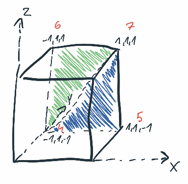
Let’s break this down.
We have four vertices that we work with:
v[4] = [-1, 1, -1]
v[5] = [1, 1, -1]
v[6] = [-1, 1, 1]
v[7] = [1, 1, 1]
We create two triangles out of them:
tri0 = [4, 6, 7]
tri1 = [4, 7, 5]
Ok, cool, now the next important thing: how UE looks uses the triangles? I mean, how UE looks at vertices of the face for normal calculation? The function looks like this:
/**
* @return normalized vector that is perpendicular to triangle V0,V1,V2  (triangle normal)
*/
template <typename RealType>
inline TVector<RealType> Normal(const TVector<RealType>& V0, const TVector<RealType>& V1, const TVector<RealType>& V2)
{
  TVector<RealType> edge1(V1 - V0);
  TVector<RealType> edge2(V2 - V0);
  Normalize(edge1);
  Normalize(edge2);
  // Unreal has Left-Hand Coordinate System so we need to reverse this cross-product to get proper triangle normal
  TVector<RealType> vCross(edge2.Cross(edge1));
  //TVector<RealType> vCross(edge1.Cross(edge2));
  return Normalized(vCross);
}
Visually it looks like this:
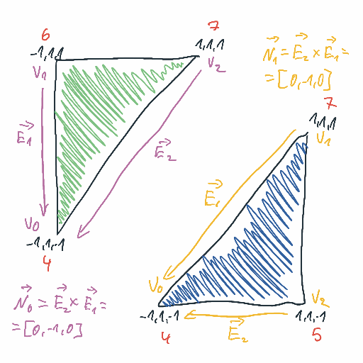
Now, here’s the problem. If we specify the triangles as we specified them:
tri0 = [4, 6, 7]
tri1 = [4, 7, 5]
The normal calculated for both of them is:
n = [0, -1, 0]
That means, the normal points inwards the mesh. It is clearly visible here. These two faces of the cube side are visible only from inside the cube.
In order to fix this, we must play nice with UE conventions and arrange the vertices accordingly to left-hand coordinate system, e.g.
tri0 = [4, 5, 6]
tri1 = [7, 5, 6]
With that, the normals are pointing outwards and the faces are rendered properly.
Back to 4D
With all this new knowledge, I wanted to get back to presenting 4D in 3D. Obeying left-hand coordinate system rules is a bit harder in a dynamically generated mesh. But, it’s doable.
In the process of generating a 3D mesh from a 4D cube at one point I end up with triangles. The triangles are represented analogically to the hardcoded ones - you just have three indices of three vertices building your triangle.
Now, what I have to do is to check if the ordering of the indices of the face obey left-hand coordinate system rules. One way to do that is check the sign of a dot product of the normal and of some point laying on inside the face. Visually:
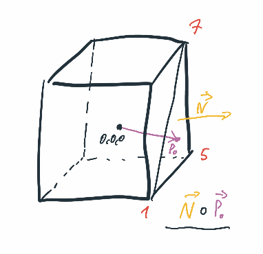
If the dot product is zero or greater than zero, then the normal points outwards, meaning the vertices are in the correct order.
If the dor product is less than zero, the normal points inwards and we need to rearrange the vertices.
In C++, I’m doing it using this simple lambda:
const auto fixTriangle = [&](int32 v0, int32 v1, int32 v2) {
  const FVector3d vertex0 = vertices[v0];
  const FVector3d vertex1 = vertices[v1];
  const FVector3d vertex2 = vertices[v2];

  const FVector3d normal =
      UE::Geometry::VectorUtil::Normal(vertex0, vertex1, vertex2);

  const FVector3d midPoint = (vertex0 + vertex1 + vertex2) / 3.0f;

  const double dot = normal.Dot(midPoint);
  if (dot < 0) {
    // Need to reverse normal by changing order of the vertices
    return UE::Geometry::FIndex3i(v0, v2, v1);
  } else {
    // Normal points out of the cube
    return UE::Geometry::FIndex3i(v0, v1, v2);
  }
};
Conclusion
There’s no magic and I was lacking elementary knowledge of how UE works. Now I understand it.
Sooo, two weeks wasted for a simple cube?